QPSK Modulation/Demodulation with GNU Radio
QPSK Modulation/Demodulation From Scratch
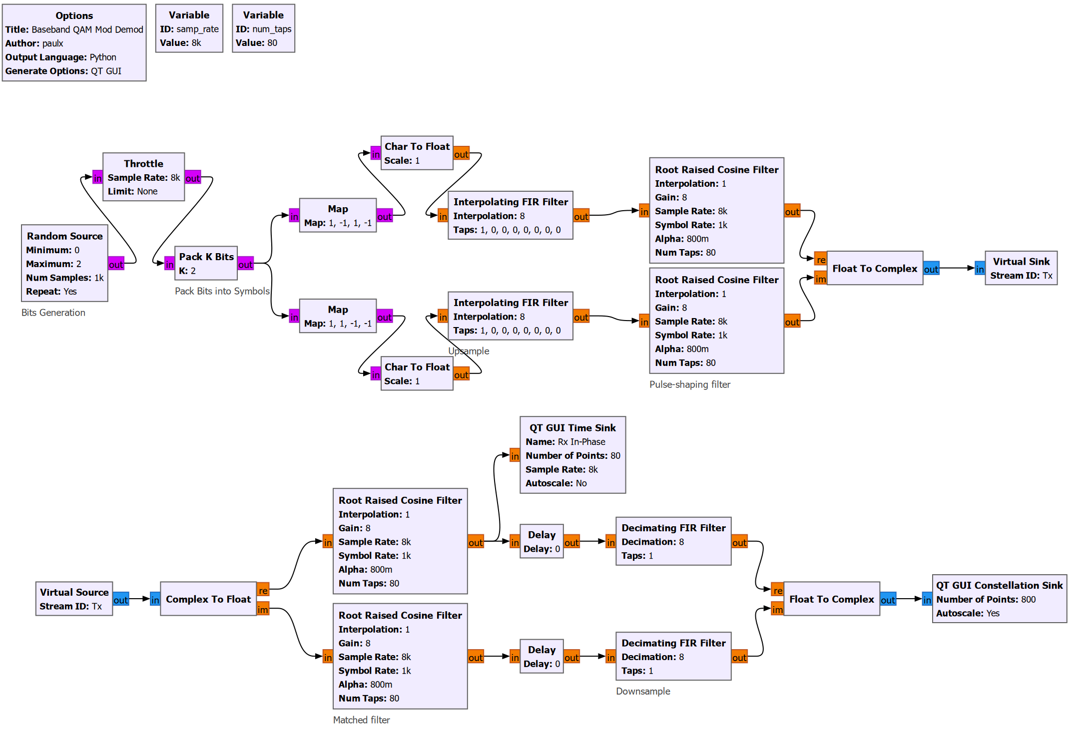
Baseband Model
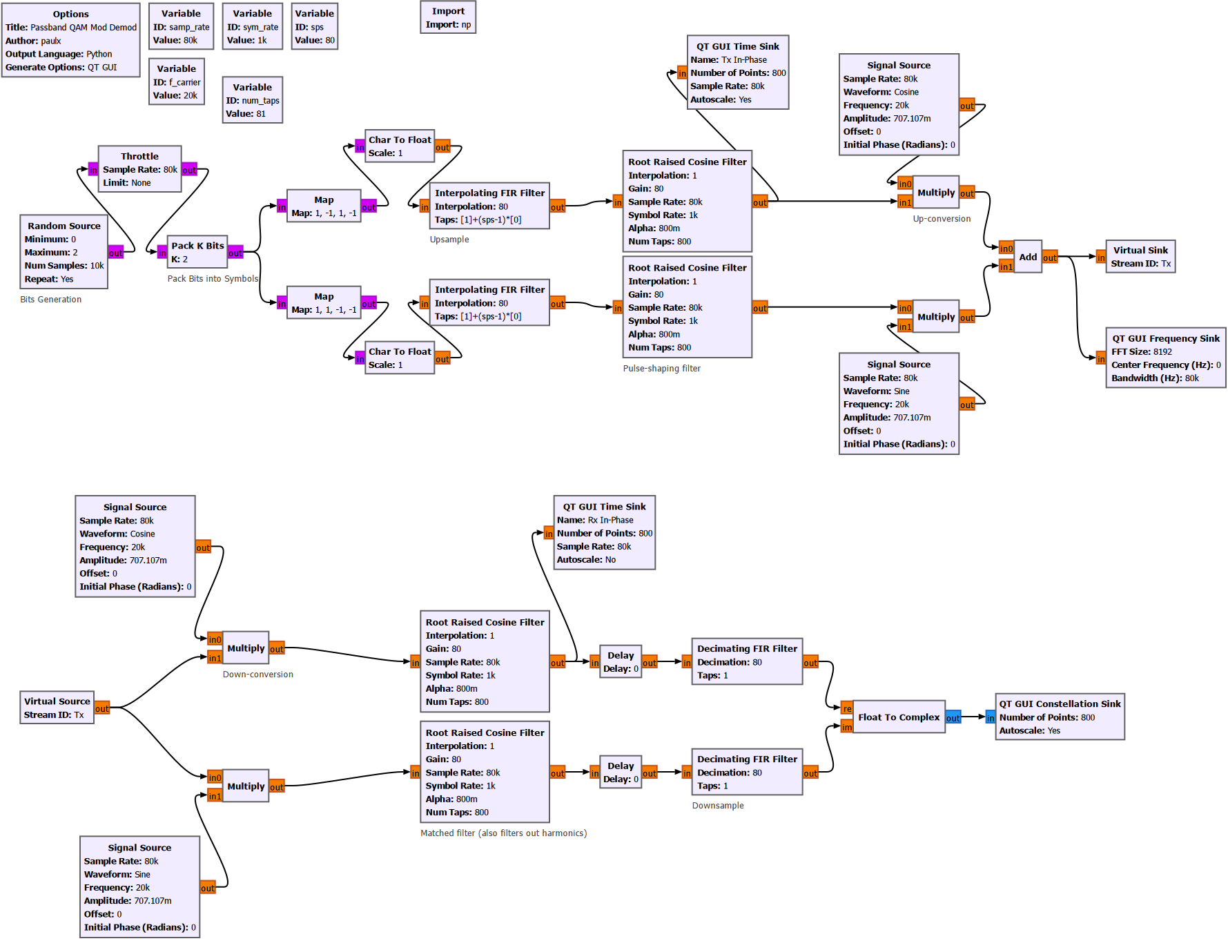
Passband Model
Note: the signs of the carriers might be incorrect. But the flow graph still illustrates the concept.
Simulation with Channel Model
The complete flow graph used for the simulation is shown below.
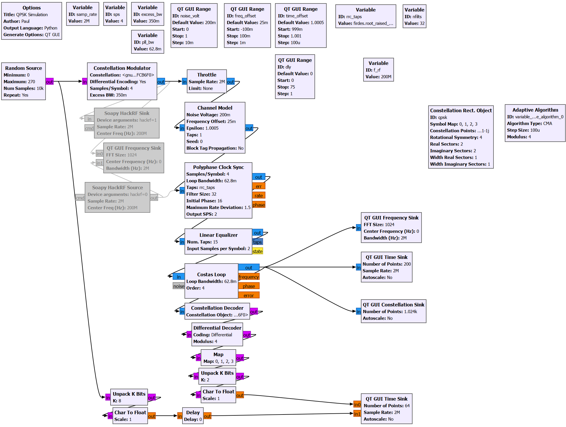
Let us explore the important blocks in the flow graph.
Random Source
This block generates a random stream of samples with levels between Minimum and Maximum. The total number of samples generated is given by Num of Samples.
Here, the output type is byte, which can represent an integer between 0 and 255. So we can potentially use this flow graph to simulate modulation order of up to 256-QAM.
Constellation Modulator
This block takes each byte generated by the random source and maps it to a QAM constellation point. The output is a stream of complex number.
Here are the key arguments for this block:
- Constellation
- Specifies the Constellation object used to map the input bytes to complex numbers.
- Samples/Symbol
- Dictates the symbol rate of our transmitted signal.
- Symbol Rate = Samples per Symbol \(\times\) Sample Rate
- Excess Bandwidth
- Determines the (root-raised cosine) pulse shaping filter, which suppresses out-of-band energy.
- Differential Encoding
- Specifies whether or not differential encoding is used.
Constellation Rect. Object
A rectangular constellation object. This block serves as a map which translates the random integers generated by the Random Source block to a complex numbers corresponding to a grid on the I/Q plane (a constellation).
Throttle
Since we are running a simulation with no actual hardware, we need to add this block to prevent the flow graph from consuming too much processing power. In fact, the flow graph will try to run as fast as out CPU can handle.
When there are rate-limiting hardware attached, such as a software-defined radio (which has a limited sample rate), this block is not needed.
Detailed Explanation for the Throttle Block
The purpose of this block is explained very well by a Reddit post [here](https://www.reddit.com/r/GNURadio/comments/1d4pz1u/sample_rates_why_cant_i_slow_down_gnuradio/). I have copied the answer here for easy reference. TLDR: if you don't have a radio to enforce a real-world speed, then you want a Throttle block somewhere in your graph. The thing to remember about GNURadio is that it is not designed to limit its processing to real-time. It runs as fast as the processor can execute the code in the various blocks. Execution is opportunistic: if a block has sufficient data in its input buffers and sufficient space to write into its output buffers, it will be scheduled and will execute as soon as the CPU has time to run it. At any given time, a flow graph has a buffer that is currently limiting the speed of the overall system. Examples: - The output buffer of a source block that is waiting for data from the world outside GNURadio (like those coming in from a physical radio receiver) - The input buffer of a sink block that is waiting to send data to the outside world (like the input to a physical radio transmitter) - The input buffer to a complex processing block, which slows down upstream blocks (who have to wait for somewhere to put their outputs) and slows down downstream blocks (who have no input to process yet) (Keep in mind that the output buffer of one block is the same buffer as the input buffer to the next block in the graph.) In most cases where there is a physical radio involved, assuming you're not getting overruns or underruns reported by the radio, then the sample rate of that radio limits the flow graph's execution speed. GNURadio Companion creates a bit of confusion by supplying a "sample_rate" variable for every new graph, but that's just a number being assigned to a variable named "sample_rate". A graph does not inherently have a sample rate; instead, that's just the variable name used by default for most physical hardware blocks. If your graph has no hardware clock limiting its execution speed, then "sample_rate" is not used to set the processing rate. Long story short - if you don't have a hardware clock limiting the rate of your flow graph but you still want to "emulate" a fixed sample rate, then you want a Throttle block. The Throttle block's job is to use the system clock to determine when to copy output from its input buffer to its output buffer. By doing so, it limits the speed of the whole flow graph. However, you almost never want a Throttle block in a flow graph that has a real radio, so be sure to remove or bypass it when you get the real radio going.Channel Model
As the name suggests, this block is used to emulate a channel over which the signal propagates. The key parameters are:
- Noise Voltage
- Used to generate additive white Gaussian noise (AWGN) which degrades the signal-to-noise ratio (SNR).
- Frequency Offset
- Used to simulate frequency offset between the transmitter and the receiver. (e.g. due to doppler shift or oscillator drift)
- Epsilon
- used to simulate timing offset between the transmitter and the receiver.
- Taps
- used to simulate multi-path propagation. It is specified as an FIR filter.
Polyphase Clock Sync
This block is used to synchronize the clock of the receiver with the clock of the transmitter. It does so using a [polyphase filter bank]https://paulxu.me/2025/08/25/polyphase-channelizer.html).
We will explore this block in more detail in another post. For now, just know that this block is needed so that we can sample the received signal at the correct instances in time.
Additionally, this block performs matched filtering and downsamples the received signal.
Linear Equalizer
The equalizer ensures that all received symbols have approximate the same amplitude.
In this example, since we are using QPSK modulation, we can use a relatively simple blind equalizer which takes advantage of the knowledge that the symbols are supposed to have constant modulus. The employed equalization algorithm is specified in the Adaptive Algorithm block.
Costas Loop
Ths Costas loop is a control loop used for carrier phase synchronization. It ensures that even in the presence of channel impairments such as doppler shift and oscillator mismatch, we are still able to correctly demodulate the received signal.
Constellation Sink
This block is used to display the constellation of the received signal.